FIUFIRST INTELLIGENCE
UTILITY
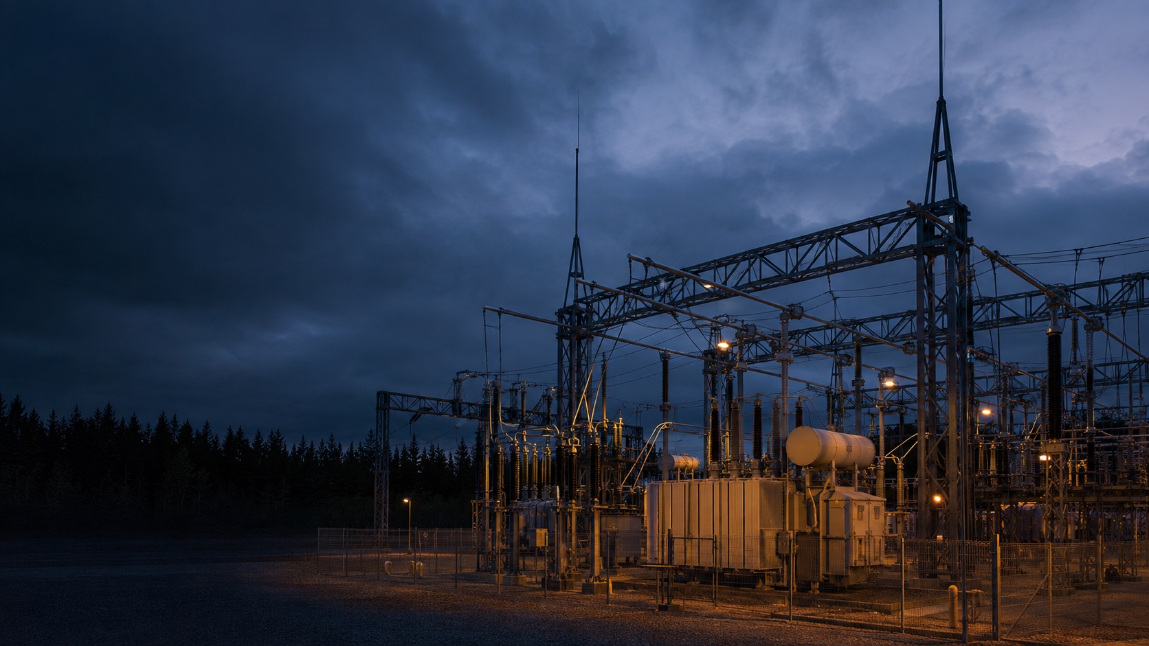
Illustrative concept render of electrical infrastructure at dusk

POWER-FIRST INFRASTRUCTURE

Power first.
Intelligence follows.

The next generation of intelligence starts with power.
We connect energy, infrastructure and capital to make it possible.

Explore our power-first approach
+ POWER / THE STARTING POINT
01 / THE FIRST INTELLIGENCE UTILITYFrom energy to infrastructure

01 / POWER FIRST

Before the campus.
Before the compute. Power.

FIU starts with the power question: where it comes from, how it reaches the site, and how it supports the workload. We bring energy, land, engineering and capital into one coordinated development sequence.

FIU / POWER IN MOTION

01/ 06
01 / PRIVATE WIRE

A direct route to power.

Solar, wind and hydro are illustrated renewable generation options; small modular reactors (SMRs) represent a future nuclear option. The generation mix and private-wire routes depend on site conditions, approvals and supply agreements. Receiving equipment connects generation to the BESS-led site network.
02 / BATTERY-LED POWER

Resilience at the centre.

The design requirement is 6–8 hours of reserve for total campus demand, including IT, cooling and auxiliaries. It is protected from grid-service dispatch and available during a supply outage. Each project requires detailed sizing and verification.

03 / GRID BACKUP

A separate route. Added resilience.

The grid provides backup into the same site network, with storage supporting continuity.

04 / GRID BALANCING & SUPPORT

Campus first. Capacity for the grid.

Private wire stays active while the BESS supports both campus supply and grid export through the common site AC bus. Campus demand is unchanged. Grid balancing uses only battery energy above the protected campus reserve, within available converter and connection capacity.

05 / POWERED INFRASTRUCTURE

Energy becomes infrastructure.

The BESS-led network serves the data halls. GPU racks are housed inside; external heat-rejection equipment supports the cooling system.

06 / POWERED COMPUTE

Infrastructure becomes intelligence.

Inside the hall, electrical distribution powers the GPU racks. A cooling distribution unit (CDU) transfers heat from the rack coolant to a separate facility-water circuit, connected to outdoor dry coolers. Blue shows coolant supply; copper shows return.

THE OPERATING ARCHITECTURE

Storage at the centre.
The campus comes first.

Private wire and the BESS conversion branch connect to a common site AC bus. That network supplies the campus and connects to the grid interface. During balancing, private wire remains active and BESS discharge supports both campus supply and grid export. The campus reserve is designed for 6–8 hours and protected from grid-service dispatch. It can supply the campus during an outage and must be restored before grid-service export resumes.

Private
wire
BESS-led systemCommon AC bus
Storage · conversion · controls
Campus reserve design: 6–8 h
DC
campus
Grid interfaceBackup supply · stored-energy export

01

Private-wire supply

Generation → private wire → BESS-led system → DC campus

The central system combines battery storage, power conversion, distribution and controls. Incoming supply serves the campus through that network; available surplus can charge storage. It does not all have to cycle through battery cells. Generation and private-wire routes are assessed for each site. Small modular reactors are a future nuclear option, subject to technology availability, approvals and supply agreements.

02

Battery reserve

Battery storage → power conversion → DC campus

The design requirement is 6–8 hours of reserve for total campus demand, including IT, cooling and auxiliaries. Grid balancing cannot use this reserved energy. It can be drawn down during an outage and must be replenished before grid-service export resumes. Duration requires project-specific sizing for usable energy, conversion losses, degradation and the supported load. Uninterrupted supply also requires suitable protection, changeover and islanding design; reserve duration alone does not establish that performance.

03

Grid backup

Grid backup → BESS-led system → DC campus

The separate grid interface provides the fallback infeed. Battery storage bridges interruptions and supports the transition. Grid imports can serve campus demand through the site network without first being stored.

04

Grid balancing and support

Private wire + BESS discharge → site AC bus → campus supply + grid export

The energy management system prioritises the full campus load and protects its 6–8-hour reserve. Balancing uses only battery energy above that reserve and available converter and connection capacity. Export is reduced or stopped before those limits are reached. The illustrated grid-connected arrangement requires an export-capable, synchronised and protected grid interface; export stops if the grid connection is lost. The energy management system coordinates grid requests and BESS dispatch. Solid green paths show site supply and solid teal shows grid export. Campus load is not curtailed.

Illustrative 3D architecture, without project-specific locations, layouts or capacities. The protected 6–8-hour reserve is a design requirement, subject to detailed sizing and verification. Green paths show site supply, amber shows grid backup and solid teal shows grid export. Blue supply and copper return pipes show two separate cooling circuits coupled at the CDU. Blue water movement at the hydro station is separate from its green electrical feed.

THE CONNECTED DEVELOPMENT WORKSTREAMS

Start with a credible route to power.

Understand the generation, connection and delivery constraints together. A viable power strategy is the foundation of the development proposition.

Design for the workload that must keep running.

Coordinate supply, storage, backup and electrical architecture around the buyer’s continuity requirements. The quality of power matters alongside its availability.

Bring the site to the power strategy.

Resolve land, planning, access and connectivity in parallel with the energy system. Build a coherent development position around the interfaces that matter.

Turn energy access into usable infrastructure.

Align power, cooling, resilience and phasing with the intended workload. Define a campus around the operator’s requirements from the start.

Make the whole system financeable.

Sequence the evidence, engineering and commercial commitments that support investment. Carry that coordination through delivery and the life of the asset.

01

Start with deliverable power.

Understand the physical, contractual and planning route from energy source to site.

02

Design for continuity.

Align supply, storage and electrical infrastructure with the demands of the workload.

03

Connect the investment case.

Bring power economics, development risk and long-term ownership into one proposition.

02 / ENERGY INTO INFRASTRUCTURE

A connection is the beginning.
The value is in the whole system.

Generation, grid access and storage have to work together. So do the technical design, the buyer’s requirements and the capital behind them.

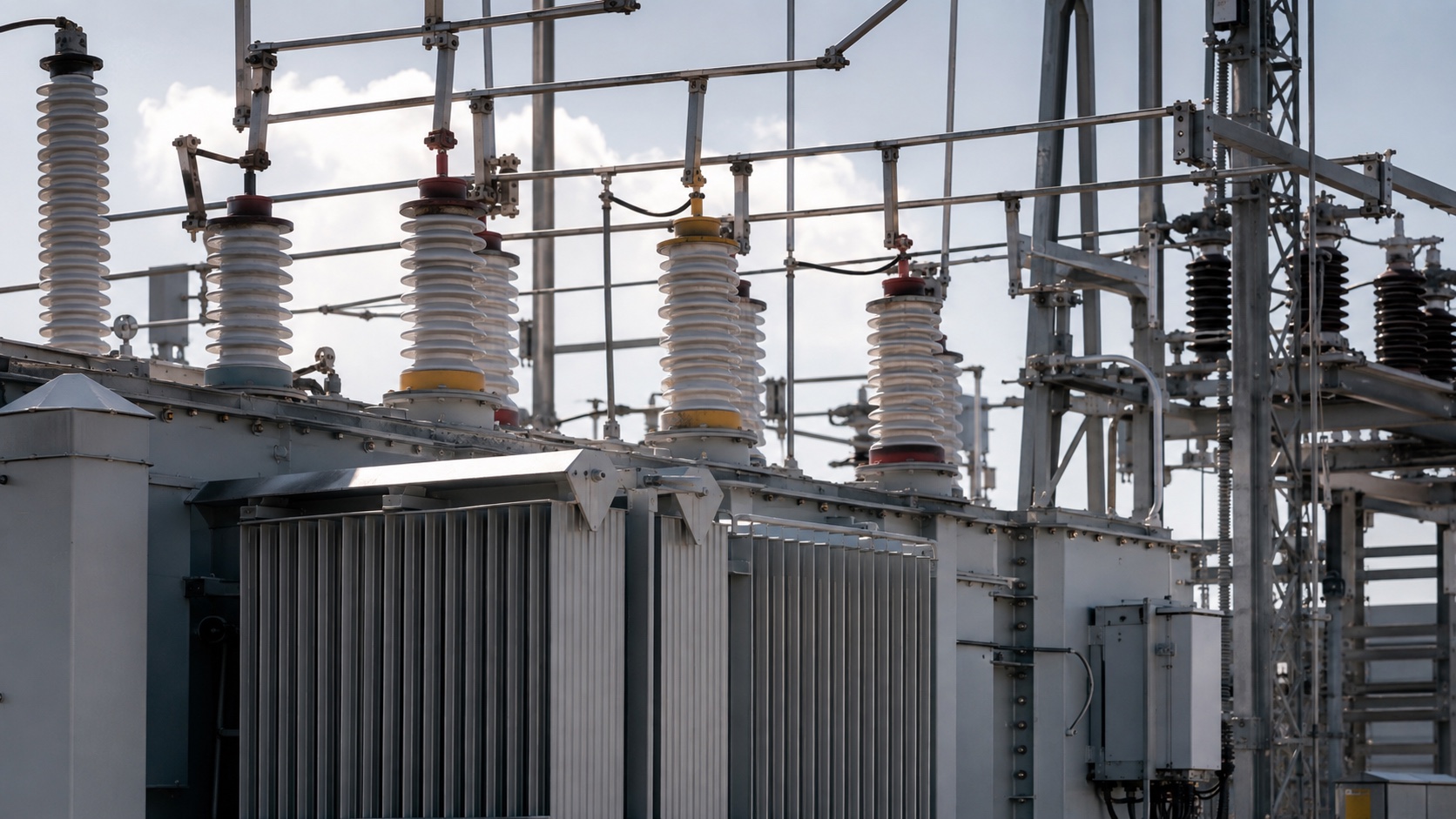
Illustrative photorealistic render of transformer and substation equipment
POWER INFRASTRUCTURE Illustrative concept render
01 / ENGINEER THE POWER POSITION

From available energy.
To dependable power.

A grid connection is one part of the answer. FIU brings the supply strategy, electrical architecture, storage and resilience requirements into the development process together.

The aim is a power proposition that the operator can use and the investor can understand.

Explore the power system
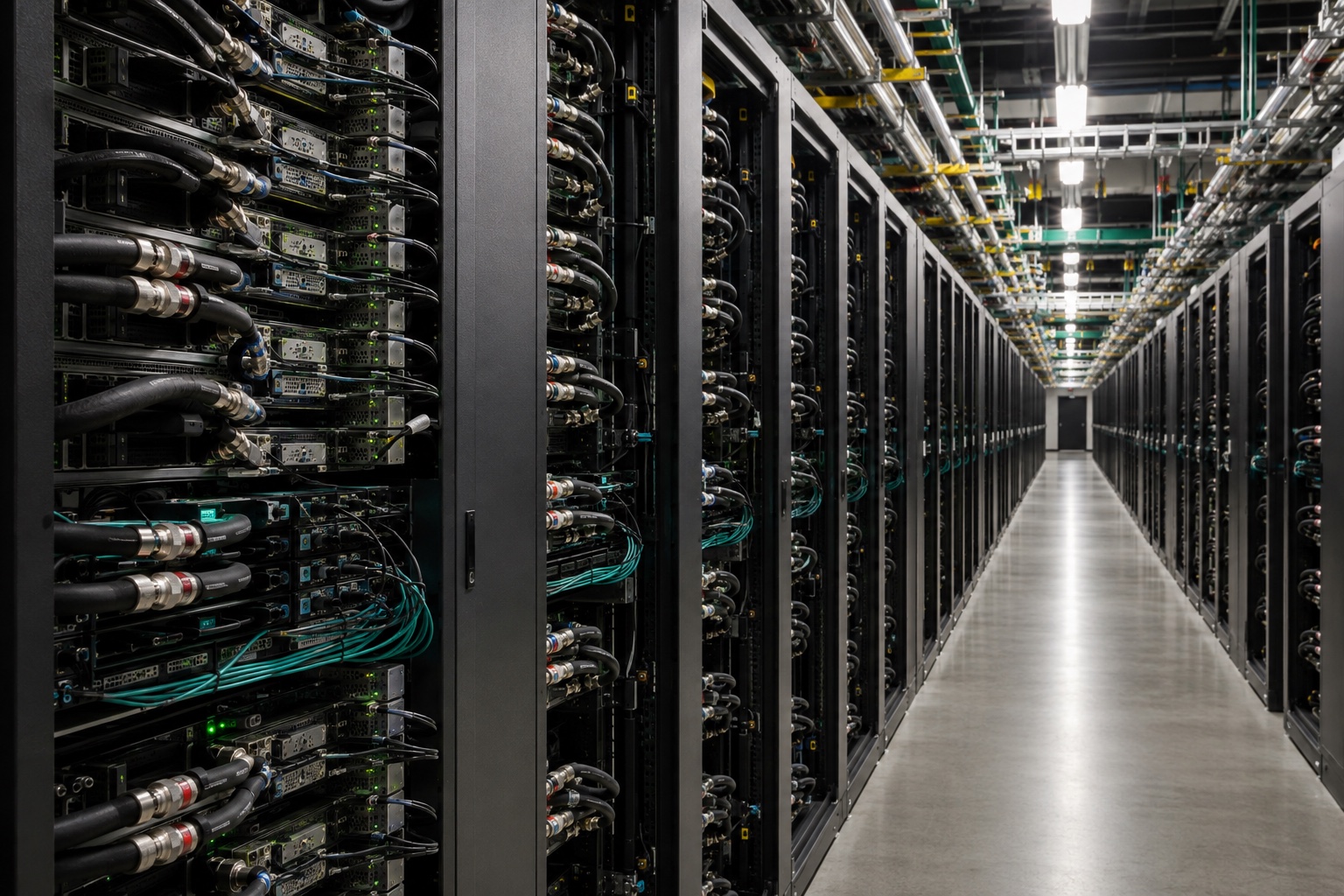
Illustrative operating GPU data-centre aisle with densely populated server racks, liquid-cooling connections and status lights
POWERED COMPUTE Illustrative GPU infrastructure render
02 / DEVELOP AROUND THE END USER

Power defines the opportunity.
The buyer shapes the campus.

FIU develops powered shells and complete data-centre infrastructure around customer requirements. Each project defines the buildings, power systems, cooling and supporting services we deliver.

FIU connects that engineering definition to capital formation and delivery, preserving the value created across the system.

Explore the integrated approach

03 / THE INTELLIGENCE LAYER

A clear path forward.
Evidence at every step.

From a power opportunity to operating infrastructure, FIU coordinates the decisions, dependencies and evidence that move development forward. Explore the sequence — and the work that must happen together.

THE FIU DEVELOPMENT SYSTEM

Power-led. Evidence-driven.

Select a stage to explore
its dependencies and evidence.
Intelligence and evidence at every stage

Origination, qualification and coordinated decisions — informed by measurement and verified performance.

ALL REQUIRED EVIDENCE CONVERGES

Construction readiness.
Not yet proof of energisation.

Measured outcomes inform the next opportunity, design and capital decision.

04 / THE INVESTMENT THESIS

The interfaces
are the investment.

A power-first approach creates the foundation. Coordinating land, campus, capital and delivery turns it into an investable infrastructure proposition.

Demand is not the binding problem. Coordinated, powered and consented delivery capacity is.

Data-centre demand, grid access, land, planning, generation, cooling and project capital are typically originated by different parties on different timetables. FIU coordinates these dependencies before a buyer or investor is asked to price delivery risk.

Originate scarce capacity before the market recognises its highest use.

Agentic origination qualifies opportunities against power, connectivity, latency, water, consent and commercial criteria. The aim is to secure the physical and contractual control required for a buyer-ready development vehicle.

Build the operating and commercial architecture into the vehicle from inception.

Development, service and lifecycle rights are connected to the asset through ownership changes. Capital is structured around stage-gated risk reduction, with funding matched to the risk that remains.

Preserve continuity across the life of the asset.

FIU coordinates grid, power, planning, engineering, construction and buyer requirements through ready-to-build conversion and delivery. Reconfiguration and compute refresh are planned lifecycle events.

FIRST INTELLIGENCE UTILITY

From possibility.
To powered infrastructure.

Explore the FIU approach